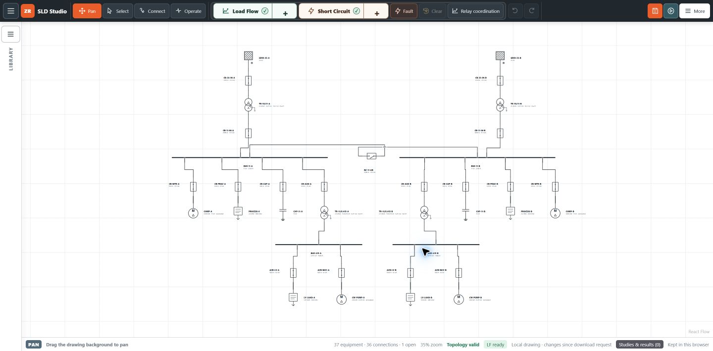
A transformer replacement, a bus-tie change or a new generator can change the fault duty at an existing board. The circuit breakers may still carry the normal load, yet their short-circuit ratings need another look.
A short circuit study for circuit breaker rating checks connects the network model to the actual devices. It should establish which current quantity is being compared, the operating case that produces it, and the manufacturer rating that applies. A single bus kA number cannot settle all of those questions.
Start with the decision you need to make
Are you checking installed breakers after a supply change, reviewing a proposed switchboard, or preparing a replacement specification? Name the boards and devices in scope, the proposed change and the information missing from the existing study.
Keep the conclusion specific: a comparison of calculated duties against documented ratings for stated cases. It does not establish the physical condition of an installed breaker or replace its maintenance and testing records.
Schneider Electric’s circuit-breaker selection guide considers installation characteristics, fault current, protected equipment and coordination. Breaking capacity is one part of selection; it is not the whole specification.
Match the duty to the correct breaker rating
Record the exact manufacturer, model, trip unit, applicable product standard and rating at the operating voltage. The table below uses common low-voltage terminology. For other equipment or rating systems, use the device’s stated basis rather than transferring these labels without checking.
| Item | What needs checking |
|---|---|
| Continuous-current rating | Normal load and installation conditions. An ampere rating does not identify short-circuit breaking capacity. |
| Breaking capacity | The applicable fault-current duty and voltage. For industrial LV breakers, distinguish ultimate capacity Icu from service capacity Ics. |
| Making capacity, Icm | The relevant peak duty. Peak current and RMS current are different quantities. |
| Short-time withstand, Icw | Current and stated duration, where this rating applies. Consider the intended protection delay. |
| Assembly capability | The board and busbar ratings as a separate part of the review. A suitable breaker rating does not establish assembly suitability. |
ABB’s explanation of short-circuit values distinguishes the rating definitions and equipment standards. Use the current datasheet for your device and agree the project’s acceptance criteria before recording a finding.
Prepare the data before requesting a study
A useful enquiry includes an up-to-date SLD and a list of equipment to be reviewed. Ask for uncertain inputs to be identified, not silently filled with typical values.
- Supply: utility maximum and minimum fault information, voltage, frequency and reference location, plus available source impedance and X/R data.
- Transformers: ratings, ratios, impedance, tap positions, vector groups and grounding arrangements.
- Conductors: cable or line types, lengths, sizes, parallel runs and impedance information.
- Other sources: generator, motor and inverter details relevant to fault contribution and the selected calculation method.
- Breakers and protection: legible nameplates, manufacturer datasheets, device identifiers, CT data, settings and operating times.
- Operating rules: normally open points, permitted source combinations and transfer arrangements.
Ground-fault cases also need suitable earthing and sequence data. If the breaker model or its applicable rating is unknown, that comparison remains unresolved until supporting information is obtained.
Illustrative case matrix: an existing plant board
Consider board DB-A, supplied through transformer T1, with standby generator G1 and a normally open tie to another transformer. CB-IN is the incomer and CB-F supplies a remote distribution board. This is a planning example, not a calculated ZeroRiskk result.
| Case to define | Inputs to confirm | Question to investigate |
|---|---|---|
| Normal supply | T1 in service, tie open, generator state documented. | What duties arise at DB-A and the remote board? |
| Permitted parallel supply | Tie closed only if this operation is allowed; both source paths modeled. | Does an additional source increase duty at a reviewed device? |
| Standby supply | G1 characteristics and the actual transfer arrangement. | How do the changed source and fault path affect duty and protection? |
| Relevant minimum-current case | Least-source arrangement, conductor assumptions and applicable fault type. | Will protection detect and clear a remote fault within the required time? |
Do not assume parallel operation is permitted because the diagram contains a tie. Also separate total bus fault current from the contribution passing through each breaker: CB-IN and CB-F need results associated with their own current paths.
Maximum-duty checks and minimum-current protection checks serve different purposes. Schneider’s minimum short-circuit current guide explains why lower fault currents also need clearance checks. The largest three-phase result alone does not complete the review.
What to ask for in the report
Before commissioning the work, agree a device-by-device schedule linking each finding to its supporting calculation and rating evidence. Request:
- The network revision, study boundary, calculation method, fault types and operating cases.
- A traceable input schedule separating verified data, assumptions and missing information.
- The fault location, current quantity, units and relevant current through each reviewed device.
- The manufacturer’s applicable rating, operating voltage and any duration or application conditions.
- A clear comparison, unresolved items and recommended follow-up, with references to the affected equipment.
If a quantity needed for a rating check is outside the calculation scope, the report should say so. Any reliance on an upstream current-limiting device or backup combination also needs applicable manufacturer evidence; it should not be assumed from two breaker ratings.
Using online short circuit analysis for breaker duty
ZeroRiskk SLD Studio connects a browser-based SLD, equipment inputs and study cases. Its software overview describes fault-current and source-contribution review, including current through interrupting devices against supplied equipment data.
When evaluating short circuit analysis software for switchgear, check the quantities, assumptions and findings available for your case before relying on a comparison. Numerical studies require sign-in; review the workspace’s displayed access and study requirement before running or paying.
New to the workspace? Use the practice network and first-study tutorial to learn the controls. For the relationship between fault studies, operating conditions and protection response, read the connected power-system study guide.
Request a scope around your actual equipment
Start with your SLD revision, voltage levels, breaker list, proposed change and permitted operating arrangements. Explain which records are available and which are missing. Scope, deliverables, fees and schedule can then be discussed for the project.
Request a breaker-duty study → or explore SLD Studio. The enquiry page prepares an email draft; it does not send automatically or upload project files.
Questions before you proceed
Does a higher ampere rating mean greater breaking capacity?
No. Continuous-current and short-circuit ratings describe different duties. Check the exact device data at the intended voltage.
Does a breaker-duty study replace relay coordination?
No. Equipment-duty comparisons and protection timing are related but separate checks. Include sensitivity, clearing times and coordination in the agreed scope where required.
Can the study approve a breaker without its datasheet?
An unknown rating cannot support a completed comparison. Record the gap and obtain the correct manufacturer information before concluding suitability.