These are provisional teaching inputs and relay settings. Some example duties fail or remain indeterminate. Reproducing a result demonstrates software use; it does not approve the electrical design or authorize relay settings for service.
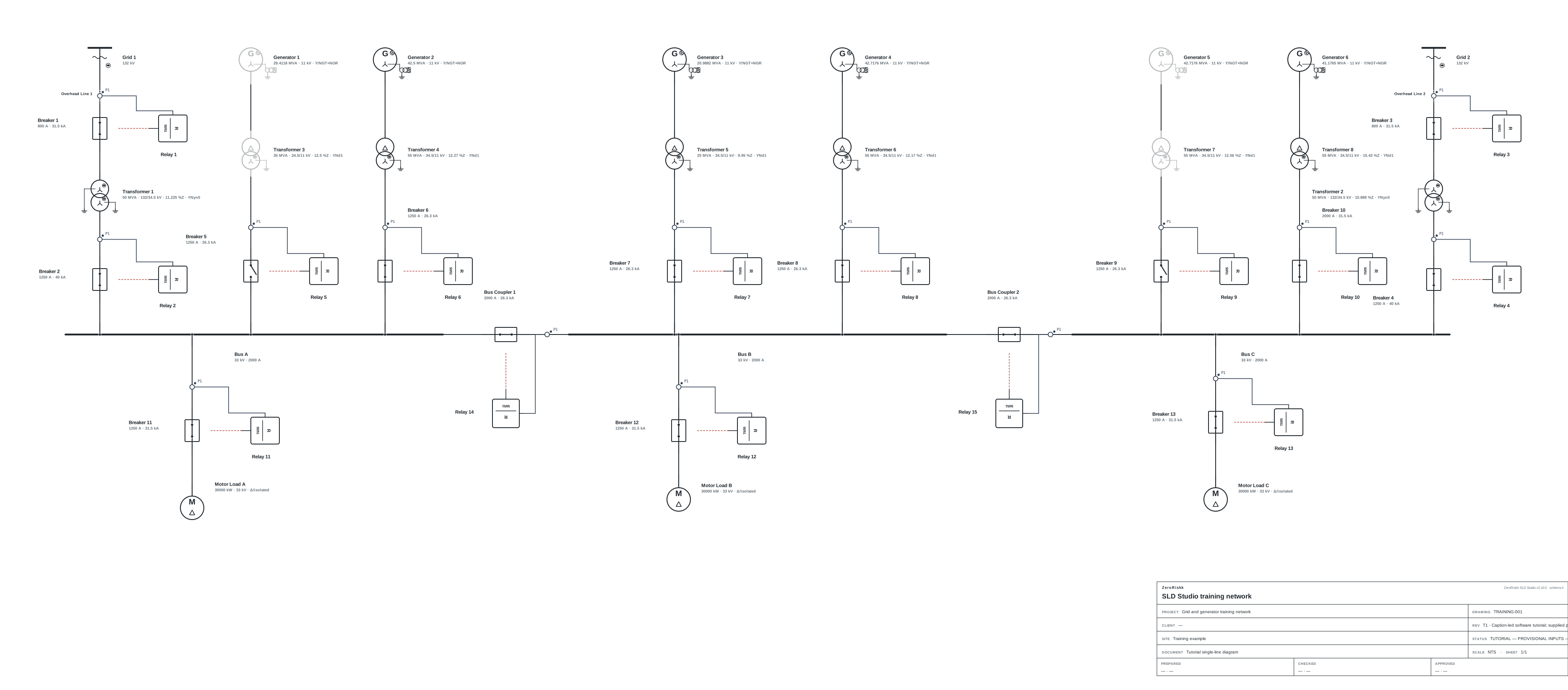
| Branch | Connect in this order |
|---|---|
| Grid incomer 1 | Grid 1 → Overhead Line 1 → Breaker 1 → Transformer 1 → Breaker 2 → Bus A |
| Grid incomer 2 | Grid 2 → Overhead Line 2 → Breaker 3 → Transformer 2 → Breaker 4 → Bus C |
| Generator branch 1 | Generator 1 → Transformer 3 → Breaker 5 → Bus A |
| Generator branch 2 | Generator 2 → Transformer 4 → Breaker 6 → Bus A |
| Generator branch 3 | Generator 3 → Transformer 5 → Breaker 7 → Bus B |
| Generator branch 4 | Generator 4 → Transformer 6 → Breaker 8 → Bus B |
| Generator branch 5 | Generator 5 → Transformer 7 → Breaker 9 → Bus C |
| Generator branch 6 | Generator 6 → Transformer 8 → Breaker 10 → Bus C |
| Motor feeder A | Bus A → Breaker 11 → Motor Load A |
| Motor feeder B | Bus B → Breaker 12 → Motor Load B |
| Motor feeder C | Bus C → Breaker 13 → Motor Load C |
| Bus coupler 1 | Bus A → Bus Coupler 1 → Bus B |
| Bus coupler 2 | Bus B → Bus Coupler 2 → Bus C |
Open the complete drawing at full size. The completed SLD download is the editable electrical model.
Open an equipment item with a double-click or Edit properties. The field names and units below match the study forms. Some inputs appear under the full Load flow, Short circuit or Earthing tabs rather than Essentials. Expand advanced sections when needed. A blank field is not zero: leave unspecified values blank and review any resulting warning.
Use these schedules for every repeated branch. The neutral-grounding-transformer symbol and its actual electrical grounding resistance are both included where used. Check both.
| Form / tab | Field | Value | Unit |
|---|---|---|---|
| Drawing | System voltage | 132 | kV |
| Drawing | In service | Yes | — |
| Drawing | Grounding symbol | auto | — |
| General | Data source | Engineering assumption | — |
| General | Rated / nominal voltage | 132 | kV |
| Load flow | Voltage setpoint | 1 | pu |
| Load flow | Voltage angle | 0 | ° |
| Short circuit | Maximum short-circuit level | 5700 | MVA |
| Short circuit | Maximum-case X/R | 20 | — |
| Short circuit | Minimum short-circuit level | 1000 | MVA |
| Short circuit | Minimum-case X/R | 7 | — |
| Earthing | Default grounding arrangement | Solidly grounded | — |
| Earthing | X0 / X1 ratio | 1 | — |
| Earthing | R0 / X0 ratio | 0.0714285714286 | — |
| Short circuit | X2 / X1 ratio | 1 | — |
| Short circuit | R2 / R1 ratio | 1 | — |
| Earthing | Source neutral resistance | 0 | Ω |
| Earthing | Source neutral reactance | 0 | Ω |
| Form / tab | Field | Value | Unit |
|---|---|---|---|
| Drawing | System voltage | 11 | kV |
| Drawing | In service | No | — |
| Drawing | Grounding symbol | neutral-grounding-transformer | — |
| Drawing | Grounding transformer primary voltage (V) | 6350 | — |
| Drawing | Grounding transformer secondary voltage (V) | 110 | — |
| Drawing | Grounding transformer secondary resistance (Ω) | 0.4 | — |
| General | Data source | Engineering assumption | — |
| General | Rated / nominal voltage | 11 | kV |
| General | Rated apparent power | 29.4118 | MVA |
| General | Rated active power | 25 | MW |
| General | Rated power factor | 0.85 | — |
| Load flow | Generator control mode | Voltage control · P + V (AVR) | — |
| Load flow | Operating active power | 0 | MW |
| Load flow | Reactive-power direction | Supply reactive power (+Q) | — |
| Load flow | Voltage setpoint | 1.02 | pu |
| Load flow | Reference voltage angle | 0 | ° |
| Load flow | Minimum reactive power · Qmin | -7.5 | MVAr |
| Load flow | Maximum reactive power · Qmax | 15 | MVAr |
| Load flow | Reactive sharing at this bus | Proportional to rated MVA | — |
| Load flow | Reactive participation weight | 1 | — |
| Short circuit | Include generator fault contribution | No | — |
| Short circuit | Subtransient reactance Xd″ | 15 | % |
| Short circuit | Subtransient X/R | 45 | — |
| Short circuit | Method C fictitious resistance Rf | 1.05 | % on machine base |
| Short circuit | Negative-sequence reactance X2 | 15 | % |
| Short circuit | Negative-sequence X2/R2 | 20 | — |
| Short circuit | Permanent generator-voltage deviation | 0.5 | % |
| Earthing | Default grounding arrangement | Resistance grounded | — |
| Earthing | Stator connection | Star | — |
| Earthing | Zero-sequence reactance X0 | 10 | % |
| Earthing | Zero-sequence X0/R0 | 8 | — |
| Earthing | Neutral resistance | 1332.97520661 | Ω |
| Earthing | Neutral reactance | 0 | Ω |
| Form / tab | Field | Value | Unit |
|---|---|---|---|
| Drawing | System voltage | 11 | kV |
| Drawing | In service | Yes | — |
| Drawing | Grounding symbol | neutral-grounding-transformer | — |
| Drawing | Grounding transformer primary voltage (V) | 6350 | — |
| Drawing | Grounding transformer secondary voltage (V) | 110 | — |
| Drawing | Grounding transformer secondary resistance (Ω) | 0.4 | — |
| General | Data source | Engineering assumption | — |
| General | Rated / nominal voltage | 11 | kV |
| General | Rated apparent power | 42.5 | MVA |
| General | Rated active power | 34.64 | MW |
| General | Rated power factor | 0.85 | — |
| Load flow | Generator control mode | Voltage control · P + V (AVR) | — |
| Load flow | Operating active power | 25.2650210108 | MW |
| Load flow | Reactive-power direction | Supply reactive power (+Q) | — |
| Load flow | Voltage setpoint | 1.00125 | pu |
| Load flow | Reference voltage angle | 0 | ° |
| Load flow | Minimum reactive power · Qmin | -12.75 | MVAr |
| Load flow | Maximum reactive power · Qmax | 22.3882642248 | MVAr |
| Load flow | Reactive sharing at this bus | Proportional to rated MVA | — |
| Load flow | Reactive participation weight | 1 | — |
| Short circuit | Include generator fault contribution | Yes | — |
| Short circuit | Subtransient reactance Xd″ | 15 | % |
| Short circuit | Subtransient X/R | 50 | — |
| Short circuit | Method C fictitious resistance Rf | 1.05 | % on machine base |
| Short circuit | Negative-sequence reactance X2 | 15 | % |
| Short circuit | Negative-sequence X2/R2 | 20 | — |
| Short circuit | Permanent generator-voltage deviation | 0.5 | % |
| Earthing | Default grounding arrangement | Resistance grounded | — |
| Earthing | Stator connection | Star | — |
| Earthing | Zero-sequence reactance X0 | 7.5 | % |
| Earthing | Zero-sequence X0/R0 | 9 | — |
| Earthing | Neutral resistance | 1332.97520661 | Ω |
| Earthing | Neutral reactance | 0 | Ω |
| Form / tab | Field | Value | Unit |
|---|---|---|---|
| Drawing | System voltage | 11 | kV |
| Drawing | In service | Yes | — |
| Drawing | Grounding symbol | neutral-grounding-transformer | — |
| Drawing | Grounding transformer primary voltage (V) | 6350 | — |
| Drawing | Grounding transformer secondary voltage (V) | 110 | — |
| Drawing | Grounding transformer secondary resistance (Ω) | 0.4 | — |
| General | Data source | Engineering assumption | — |
| General | Rated / nominal voltage | 11 | kV |
| General | Rated apparent power | 20.9882 | MVA |
| General | Rated active power | 17.84 | MW |
| General | Rated power factor | 0.85 | — |
| Load flow | Generator control mode | Voltage control · P + V (AVR) | — |
| Load flow | Operating active power | 13.0117775644 | MW |
| Load flow | Reactive-power direction | Supply reactive power (+Q) | — |
| Load flow | Voltage setpoint | 1.00125 | pu |
| Load flow | Reference voltage angle | 0 | ° |
| Load flow | Minimum reactive power · Qmin | -6.29646 | MVAr |
| Load flow | Maximum reactive power · Qmax | 11.0562204048 | MVAr |
| Load flow | Reactive sharing at this bus | Proportional to rated MVA | — |
| Load flow | Reactive participation weight | 1 | — |
| Short circuit | Include generator fault contribution | Yes | — |
| Short circuit | Subtransient reactance Xd″ | 14 | % |
| Short circuit | Subtransient X/R | 40 | — |
| Short circuit | Method C fictitious resistance Rf | 0.98 | % on machine base |
| Short circuit | Negative-sequence reactance X2 | 14 | % |
| Short circuit | Negative-sequence X2/R2 | 18 | — |
| Short circuit | Permanent generator-voltage deviation | 0.5 | % |
| Earthing | Default grounding arrangement | Resistance grounded | — |
| Earthing | Stator connection | Star | — |
| Earthing | Zero-sequence reactance X0 | 7 | % |
| Earthing | Zero-sequence X0/R0 | 9 | — |
| Earthing | Neutral resistance | 1332.97520661 | Ω |
| Earthing | Neutral reactance | 0 | Ω |
| Form / tab | Field | Value | Unit |
|---|---|---|---|
| Drawing | System voltage | 11 | kV |
| Drawing | In service | Yes | — |
| Drawing | Grounding symbol | neutral-grounding-transformer | — |
| Drawing | Grounding transformer primary voltage (V) | 6351 | — |
| Drawing | Grounding transformer secondary voltage (V) | 110 | — |
| Drawing | Grounding transformer secondary resistance (Ω) | 0.4 | — |
| General | Data source | Engineering assumption | — |
| General | Rated / nominal voltage | 11 | kV |
| General | Rated apparent power | 42.7176 | MVA |
| General | Rated active power | 36.31 | MW |
| General | Rated power factor | 0.85 | — |
| Load flow | Generator control mode | Voltage control · P + V (AVR) | — |
| Load flow | Operating active power | 26.4830517581 | MW |
| Load flow | Reactive-power direction | Supply reactive power (+Q) | — |
| Load flow | Voltage setpoint | 1.00125 | pu |
| Load flow | Reference voltage angle | 0 | ° |
| Load flow | Minimum reactive power · Qmin | -12.81528 | MVAr |
| Load flow | Maximum reactive power · Qmax | 22.5028921376 | MVAr |
| Load flow | Reactive sharing at this bus | Proportional to rated MVA | — |
| Load flow | Reactive participation weight | 1 | — |
| Short circuit | Include generator fault contribution | Yes | — |
| Short circuit | Subtransient reactance Xd″ | 13.5 | % |
| Short circuit | Subtransient X/R | 35 | — |
| Short circuit | Method C fictitious resistance Rf | 0.945 | % on machine base |
| Short circuit | Negative-sequence reactance X2 | 14.5 | % |
| Short circuit | Negative-sequence X2/R2 | 25 | — |
| Short circuit | Permanent generator-voltage deviation | 0 | % |
| Earthing | Default grounding arrangement | Resistance grounded | — |
| Earthing | Stator connection | Star | — |
| Earthing | Zero-sequence reactance X0 | 5.5 | % |
| Earthing | Zero-sequence X0/R0 | 4.5 | — |
| Earthing | Neutral resistance | 1333.39507438 | Ω |
| Earthing | Neutral reactance | 0 | Ω |
| Form / tab | Field | Value | Unit |
|---|---|---|---|
| Drawing | System voltage | 11 | kV |
| Drawing | In service | No | — |
| Drawing | Grounding symbol | neutral-grounding-transformer | — |
| Drawing | Grounding transformer primary voltage (V) | 6351 | — |
| Drawing | Grounding transformer secondary voltage (V) | 110 | — |
| Drawing | Grounding transformer secondary resistance (Ω) | 0.4 | — |
| General | Data source | Engineering assumption | — |
| General | Rated / nominal voltage | 11 | kV |
| General | Rated apparent power | 42.7176 | MVA |
| General | Rated active power | 36.31 | MW |
| General | Rated power factor | 0.85 | — |
| Load flow | Generator control mode | Voltage control · P + V (AVR) | — |
| Load flow | Operating active power | 0 | MW |
| Load flow | Reactive-power direction | Supply reactive power (+Q) | — |
| Load flow | Voltage setpoint | 1.02 | pu |
| Load flow | Reference voltage angle | 0 | ° |
| Load flow | Minimum reactive power · Qmin | -12.81528 | MVAr |
| Load flow | Maximum reactive power · Qmax | 22.5028921376 | MVAr |
| Load flow | Reactive sharing at this bus | Proportional to rated MVA | — |
| Load flow | Reactive participation weight | 1 | — |
| Short circuit | Include generator fault contribution | No | — |
| Short circuit | Subtransient reactance Xd″ | 13.5 | % |
| Short circuit | Subtransient X/R | 35 | — |
| Short circuit | Method C fictitious resistance Rf | 0.945 | % on machine base |
| Short circuit | Negative-sequence reactance X2 | 14.5 | % |
| Short circuit | Negative-sequence X2/R2 | 25 | — |
| Short circuit | Permanent generator-voltage deviation | 0 | % |
| Earthing | Default grounding arrangement | Resistance grounded | — |
| Earthing | Stator connection | Star | — |
| Earthing | Zero-sequence reactance X0 | 5.5 | % |
| Earthing | Zero-sequence X0/R0 | 4.5 | — |
| Earthing | Neutral resistance | 1333.39507438 | Ω |
| Earthing | Neutral reactance | 0 | Ω |
| Form / tab | Field | Value | Unit |
|---|---|---|---|
| Drawing | System voltage | 11 | kV |
| Drawing | In service | Yes | — |
| Drawing | Grounding symbol | neutral-grounding-transformer | — |
| Drawing | Grounding transformer primary voltage (V) | 6351 | — |
| Drawing | Grounding transformer secondary voltage (V) | 110 | — |
| Drawing | Grounding transformer secondary resistance (Ω) | 0.4 | — |
| General | Data source | Engineering assumption | — |
| General | Rated / nominal voltage | 11 | kV |
| General | Rated apparent power | 41.1765 | MVA |
| General | Rated active power | 35 | MW |
| General | Rated power factor | 0.85 | — |
| Load flow | Generator control mode | Voltage control · P + V (AVR) | — |
| Load flow | Operating active power | 25.5275905132 | MW |
| Load flow | Reactive-power direction | Supply reactive power (+Q) | — |
| Load flow | Voltage setpoint | 1.00125 | pu |
| Load flow | Reference voltage angle | 0 | ° |
| Load flow | Minimum reactive power · Qmin | -12.35295 | MVAr |
| Load flow | Maximum reactive power · Qmax | 21.6910673377 | MVAr |
| Load flow | Reactive sharing at this bus | Proportional to rated MVA | — |
| Load flow | Reactive participation weight | 1 | — |
| Short circuit | Include generator fault contribution | Yes | — |
| Short circuit | Subtransient reactance Xd″ | 13.5 | % |
| Short circuit | Subtransient X/R | 35 | — |
| Short circuit | Method C fictitious resistance Rf | 0.945 | % on machine base |
| Short circuit | Negative-sequence reactance X2 | 14.5 | % |
| Short circuit | Negative-sequence X2/R2 | 25 | — |
| Short circuit | Permanent generator-voltage deviation | 0 | % |
| Earthing | Default grounding arrangement | Resistance grounded | — |
| Earthing | Stator connection | Star | — |
| Earthing | Zero-sequence reactance X0 | 5.5 | % |
| Earthing | Zero-sequence X0/R0 | 4.5 | — |
| Earthing | Neutral resistance | 1333.39507438 | Ω |
| Earthing | Neutral reactance | 0 | Ω |
| Form / tab | Field | Value | Unit |
|---|---|---|---|
| Drawing | System voltage | 132 | kV |
| Drawing | In service | Yes | — |
| Drawing | Normal state | closed | — |
| Drawing | Operating state | closed | — |
| General | Data source | Engineering assumption | — |
| General | Rated / nominal voltage | 145 | kV |
| General | Rated continuous current | 800 | A |
| Short circuit | Rated breaking current | 31.5 | kA rms |
| Short circuit | Rated making current | 80 | kA peak |
| Short circuit | Short-time withstand current | 31.5 | kA rms |
| Short circuit | Short-time withstand duration | 3 | s |
| Short circuit | Total clearing time | 70 | ms |
| Form / tab | Field | Value | Unit |
|---|---|---|---|
| Drawing | System voltage | 132 | kV |
| Drawing | In service | Yes | — |
| Drawing | Normal state | closed | — |
| Drawing | Operating state | closed | — |
| General | Data source | Engineering assumption | — |
| General | Rated / nominal voltage | 145 | kV |
| General | Rated continuous current | 800 | A |
| Short circuit | Rated breaking current | 31.5 | kA rms |
| Short circuit | Rated making current | 80 | kA peak |
| Short circuit | Short-time withstand current | 31.5 | kA rms |
| Short circuit | Short-time withstand duration | 3 | s |
| Short circuit | Total clearing time | 70 | ms |
| Form / tab | Field | Value | Unit |
|---|---|---|---|
| Drawing | High-voltage terminal system voltage | 33 | kV |
| Drawing | Low-voltage terminal system voltage | 11 | kV |
| Drawing | In service | No | — |
| Drawing | Transformer application | general | — |
| Drawing | High-voltage grounding symbol | auto | — |
| Drawing | Low-voltage grounding symbol | auto | — |
| General | Data source | Engineering assumption | — |
| General | Rated power | 35 | MVA |
| General | HV rated voltage | 34.5 | kV |
| General | LV rated voltage | 11 | kV |
| General | Vector group | YNd1 | — |
| General | Short-circuit impedance | 12.5 | % |
| General | Transformer X/R | 20 | — |
| Load flow | No-load loss | 21 | kW |
| Load flow | No-load current | 0.3 | % |
| Load flow | Tap-changer side | HV winding | — |
| Load flow | Neutral tap position | 0 | — |
| Load flow | Minimum tap position | -8 | — |
| Load flow | Maximum tap position | 8 | — |
| Load flow | Current tap position | 0 | — |
| Load flow | Voltage change per tap | 1.25 | % |
| Short circuit | Apply IEC transformer correction factor KT | Yes | — |
| Earthing | Default grounding arrangement | Solidly grounded | — |
| Earthing | HV winding grounding | Solidly grounded | — |
| Earthing | LV winding grounding | Isolated neutral | — |
| Earthing | Zero-sequence connection model | Automatic from vector group | — |
| Earthing | Zero-sequence impedance | 12.5 | % |
| Earthing | Zero-sequence X/R | 20 | — |
| Earthing | HV neutral resistance | 0 | Ω |
| Earthing | HV neutral reactance | 0 | Ω |
| Earthing | LV neutral resistance | 0 | Ω |
| Earthing | LV neutral reactance | 0 | Ω |
| Form / tab | Field | Value | Unit |
|---|---|---|---|
| Drawing | High-voltage terminal system voltage | 33 | kV |
| Drawing | Low-voltage terminal system voltage | 11 | kV |
| Drawing | In service | Yes | — |
| Drawing | Transformer application | general | — |
| Drawing | High-voltage grounding symbol | auto | — |
| Drawing | Low-voltage grounding symbol | auto | — |
| General | Data source | Engineering assumption | — |
| General | Rated power | 55 | MVA |
| General | HV rated voltage | 34.5 | kV |
| General | LV rated voltage | 11 | kV |
| General | Vector group | YNd1 | — |
| General | Short-circuit impedance | 12.27 | % |
| General | Transformer X/R | 20 | — |
| Load flow | No-load loss | 33 | kW |
| Load flow | No-load current | 0.3 | % |
| Load flow | Tap-changer side | HV winding | — |
| Load flow | Neutral tap position | 0 | — |
| Load flow | Minimum tap position | -8 | — |
| Load flow | Maximum tap position | 8 | — |
| Load flow | Current tap position | 0 | — |
| Load flow | Voltage change per tap | 1.25 | % |
| Short circuit | Apply IEC transformer correction factor KT | Yes | — |
| Earthing | Default grounding arrangement | Solidly grounded | — |
| Earthing | HV winding grounding | Solidly grounded | — |
| Earthing | LV winding grounding | Isolated neutral | — |
| Earthing | Zero-sequence connection model | Automatic from vector group | — |
| Earthing | Zero-sequence impedance | 12.27 | % |
| Earthing | Zero-sequence X/R | 20 | — |
| Earthing | HV neutral resistance | 0 | Ω |
| Earthing | HV neutral reactance | 0 | Ω |
| Earthing | LV neutral resistance | 0 | Ω |
| Earthing | LV neutral reactance | 0 | Ω |
| Form / tab | Field | Value | Unit |
|---|---|---|---|
| Drawing | High-voltage terminal system voltage | 33 | kV |
| Drawing | Low-voltage terminal system voltage | 11 | kV |
| Drawing | In service | Yes | — |
| Drawing | Transformer application | general | — |
| Drawing | High-voltage grounding symbol | auto | — |
| Drawing | Low-voltage grounding symbol | auto | — |
| General | Data source | Engineering assumption | — |
| General | Rated power | 25 | MVA |
| General | HV rated voltage | 34.5 | kV |
| General | LV rated voltage | 11 | kV |
| General | Vector group | YNd1 | — |
| General | Short-circuit impedance | 9.95 | % |
| General | Transformer X/R | 20 | — |
| Load flow | No-load loss | 15 | kW |
| Load flow | No-load current | 0.3 | % |
| Load flow | Tap-changer side | HV winding | — |
| Load flow | Neutral tap position | 0 | — |
| Load flow | Minimum tap position | -8 | — |
| Load flow | Maximum tap position | 8 | — |
| Load flow | Current tap position | 0 | — |
| Load flow | Voltage change per tap | 1.25 | % |
| Short circuit | Apply IEC transformer correction factor KT | Yes | — |
| Earthing | Default grounding arrangement | Solidly grounded | — |
| Earthing | HV winding grounding | Solidly grounded | — |
| Earthing | LV winding grounding | Isolated neutral | — |
| Earthing | Zero-sequence connection model | Automatic from vector group | — |
| Earthing | Zero-sequence impedance | 9.95 | % |
| Earthing | Zero-sequence X/R | 20 | — |
| Earthing | HV neutral resistance | 0 | Ω |
| Earthing | HV neutral reactance | 0 | Ω |
| Earthing | LV neutral resistance | 0 | Ω |
| Earthing | LV neutral reactance | 0 | Ω |
| Form / tab | Field | Value | Unit |
|---|---|---|---|
| Drawing | High-voltage terminal system voltage | 33 | kV |
| Drawing | Low-voltage terminal system voltage | 11 | kV |
| Drawing | In service | Yes | — |
| Drawing | Transformer application | general | — |
| Drawing | High-voltage grounding symbol | auto | — |
| Drawing | Low-voltage grounding symbol | auto | — |
| General | Data source | Engineering assumption | — |
| General | Rated power | 55 | MVA |
| General | HV rated voltage | 34.5 | kV |
| General | LV rated voltage | 11 | kV |
| General | Vector group | YNd1 | — |
| General | Short-circuit impedance | 12.17 | % |
| General | Transformer X/R | 20 | — |
| Load flow | No-load loss | 33 | kW |
| Load flow | No-load current | 0.3 | % |
| Load flow | Tap-changer side | HV winding | — |
| Load flow | Neutral tap position | 0 | — |
| Load flow | Minimum tap position | -8 | — |
| Load flow | Maximum tap position | 8 | — |
| Load flow | Current tap position | 0 | — |
| Load flow | Voltage change per tap | 1.25 | % |
| Short circuit | Apply IEC transformer correction factor KT | Yes | — |
| Earthing | Default grounding arrangement | Solidly grounded | — |
| Earthing | HV winding grounding | Solidly grounded | — |
| Earthing | LV winding grounding | Isolated neutral | — |
| Earthing | Zero-sequence connection model | Automatic from vector group | — |
| Earthing | Zero-sequence impedance | 12.17 | % |
| Earthing | Zero-sequence X/R | 20 | — |
| Earthing | HV neutral resistance | 0 | Ω |
| Earthing | HV neutral reactance | 0 | Ω |
| Earthing | LV neutral resistance | 0 | Ω |
| Earthing | LV neutral reactance | 0 | Ω |
| Form / tab | Field | Value | Unit |
|---|---|---|---|
| Drawing | High-voltage terminal system voltage | 33 | kV |
| Drawing | Low-voltage terminal system voltage | 11 | kV |
| Drawing | In service | No | — |
| Drawing | Transformer application | general | — |
| Drawing | High-voltage grounding symbol | auto | — |
| Drawing | Low-voltage grounding symbol | auto | — |
| General | Data source | Engineering assumption | — |
| General | Rated power | 55 | MVA |
| General | HV rated voltage | 34.5 | kV |
| General | LV rated voltage | 11 | kV |
| General | Vector group | YNd1 | — |
| General | Short-circuit impedance | 12.06 | % |
| General | Transformer X/R | 20 | — |
| Load flow | No-load loss | 33 | kW |
| Load flow | No-load current | 0.3 | % |
| Load flow | Tap-changer side | HV winding | — |
| Load flow | Neutral tap position | 0 | — |
| Load flow | Minimum tap position | -8 | — |
| Load flow | Maximum tap position | 8 | — |
| Load flow | Current tap position | 0 | — |
| Load flow | Voltage change per tap | 1.25 | % |
| Short circuit | Apply IEC transformer correction factor KT | Yes | — |
| Earthing | Default grounding arrangement | Solidly grounded | — |
| Earthing | HV winding grounding | Solidly grounded | — |
| Earthing | LV winding grounding | Isolated neutral | — |
| Earthing | Zero-sequence connection model | Automatic from vector group | — |
| Earthing | Zero-sequence impedance | 12.06 | % |
| Earthing | Zero-sequence X/R | 20 | — |
| Earthing | HV neutral resistance | 0 | Ω |
| Earthing | HV neutral reactance | 0 | Ω |
| Earthing | LV neutral resistance | 0 | Ω |
| Earthing | LV neutral reactance | 0 | Ω |
| Form / tab | Field | Value | Unit |
|---|---|---|---|
| Drawing | High-voltage terminal system voltage | 33 | kV |
| Drawing | Low-voltage terminal system voltage | 11 | kV |
| Drawing | In service | Yes | — |
| Drawing | Transformer application | general | — |
| Drawing | High-voltage grounding symbol | auto | — |
| Drawing | Low-voltage grounding symbol | auto | — |
| General | Data source | Engineering assumption | — |
| General | Rated power | 55 | MVA |
| General | HV rated voltage | 34.5 | kV |
| General | LV rated voltage | 11 | kV |
| General | Vector group | YNd1 | — |
| General | Short-circuit impedance | 15.43 | % |
| General | Transformer X/R | 20 | — |
| Load flow | No-load loss | 33 | kW |
| Load flow | No-load current | 0.3 | % |
| Load flow | Tap-changer side | HV winding | — |
| Load flow | Neutral tap position | 0 | — |
| Load flow | Minimum tap position | -8 | — |
| Load flow | Maximum tap position | 8 | — |
| Load flow | Current tap position | 0 | — |
| Load flow | Voltage change per tap | 1.25 | % |
| Short circuit | Apply IEC transformer correction factor KT | Yes | — |
| Earthing | Default grounding arrangement | Solidly grounded | — |
| Earthing | HV winding grounding | Solidly grounded | — |
| Earthing | LV winding grounding | Isolated neutral | — |
| Earthing | Zero-sequence connection model | Automatic from vector group | — |
| Earthing | Zero-sequence impedance | 15.43 | % |
| Earthing | Zero-sequence X/R | 20 | — |
| Earthing | HV neutral resistance | 0 | Ω |
| Earthing | HV neutral reactance | 0 | Ω |
| Earthing | LV neutral resistance | 0 | Ω |
| Earthing | LV neutral reactance | 0 | Ω |
| Form / tab | Field | Value | Unit |
|---|---|---|---|
| Drawing | High-voltage terminal system voltage | 132 | kV |
| Drawing | Low-voltage terminal system voltage | 33 | kV |
| Drawing | In service | Yes | — |
| Drawing | Transformer application | general | — |
| Drawing | High-voltage grounding symbol | auto | — |
| Drawing | Low-voltage grounding symbol | auto | — |
| General | Data source | Engineering assumption | — |
| General | Rated power | 50 | MVA |
| General | HV rated voltage | 132 | kV |
| General | LV rated voltage | 34.5 | kV |
| General | Vector group | YNyn0 | — |
| General | Short-circuit impedance | 11.225 | % |
| General | Transformer X/R | 20 | — |
| Load flow | No-load loss | 30 | kW |
| Load flow | No-load current | 0.3 | % |
| Load flow | Tap-changer side | HV winding | — |
| Load flow | Neutral tap position | 0 | — |
| Load flow | Minimum tap position | -8 | — |
| Load flow | Maximum tap position | 8 | — |
| Load flow | Current tap position | 3 | — |
| Load flow | Voltage change per tap | 1.25 | % |
| Short circuit | Apply IEC transformer correction factor KT | Yes | — |
| Earthing | Default grounding arrangement | Solidly grounded | — |
| Earthing | HV winding grounding | Solidly grounded | — |
| Earthing | LV winding grounding | Solidly grounded | — |
| Earthing | Zero-sequence connection model | Automatic from vector group | — |
| Earthing | Zero-sequence impedance | 11.225 | % |
| Earthing | Zero-sequence X/R | 20 | — |
| Earthing | HV neutral resistance | 0 | Ω |
| Earthing | HV neutral reactance | 0 | Ω |
| Earthing | LV neutral resistance | 0 | Ω |
| Earthing | LV neutral reactance | 0 | Ω |
| Form / tab | Field | Value | Unit |
|---|---|---|---|
| Drawing | High-voltage terminal system voltage | 132 | kV |
| Drawing | Low-voltage terminal system voltage | 33 | kV |
| Drawing | In service | Yes | — |
| Drawing | Transformer application | general | — |
| Drawing | High-voltage grounding symbol | auto | — |
| Drawing | Low-voltage grounding symbol | auto | — |
| General | Data source | Engineering assumption | — |
| General | Rated power | 50 | MVA |
| General | HV rated voltage | 132 | kV |
| General | LV rated voltage | 34.5 | kV |
| General | Vector group | YNyn0 | — |
| General | Short-circuit impedance | 10.889 | % |
| General | Transformer X/R | 20 | — |
| Load flow | No-load loss | 30 | kW |
| Load flow | No-load current | 0.3 | % |
| Load flow | Tap-changer side | HV winding | — |
| Load flow | Neutral tap position | 0 | — |
| Load flow | Minimum tap position | -8 | — |
| Load flow | Maximum tap position | 8 | — |
| Load flow | Current tap position | 3 | — |
| Load flow | Voltage change per tap | 1.25 | % |
| Short circuit | Apply IEC transformer correction factor KT | Yes | — |
| Earthing | Default grounding arrangement | Solidly grounded | — |
| Earthing | HV winding grounding | Solidly grounded | — |
| Earthing | LV winding grounding | Solidly grounded | — |
| Earthing | Zero-sequence connection model | Automatic from vector group | — |
| Earthing | Zero-sequence impedance | 10.889 | % |
| Earthing | Zero-sequence X/R | 20 | — |
| Earthing | HV neutral resistance | 0 | Ω |
| Earthing | HV neutral reactance | 0 | Ω |
| Earthing | LV neutral resistance | 0 | Ω |
| Earthing | LV neutral reactance | 0 | Ω |
| Form / tab | Field | Value | Unit |
|---|---|---|---|
| Drawing | System voltage | 33 | kV |
| Drawing | In service | Yes | — |
| Drawing | Normal state | open | — |
| Drawing | Operating state | open | — |
| General | Data source | Engineering assumption | — |
| General | Rated / nominal voltage | 36 | kV |
| General | Rated continuous current | 1250 | A |
| Short circuit | Rated breaking current | 26.3 | kA rms |
| Short circuit | Rated making current | 65.75 | kA peak |
| Short circuit | Short-time withstand current | 26.3 | kA rms |
| Short circuit | Short-time withstand duration | 3 | s |
| Short circuit | Total clearing time | 70 | ms |
| Form / tab | Field | Value | Unit |
|---|---|---|---|
| Drawing | System voltage | 33 | kV |
| Drawing | In service | Yes | — |
| Drawing | Normal state | closed | — |
| Drawing | Operating state | closed | — |
| General | Data source | Engineering assumption | — |
| General | Rated / nominal voltage | 36 | kV |
| General | Rated continuous current | 1250 | A |
| Short circuit | Rated breaking current | 26.3 | kA rms |
| Short circuit | Rated making current | 65.75 | kA peak |
| Short circuit | Short-time withstand current | 26.3 | kA rms |
| Short circuit | Short-time withstand duration | 3 | s |
| Short circuit | Total clearing time | 70 | ms |
| Form / tab | Field | Value | Unit |
|---|---|---|---|
| Drawing | System voltage | 33 | kV |
| Drawing | In service | Yes | — |
| Drawing | Normal state | closed | — |
| Drawing | Operating state | closed | — |
| General | Data source | Engineering assumption | — |
| General | Rated / nominal voltage | 36 | kV |
| General | Rated continuous current | 1250 | A |
| Short circuit | Rated breaking current | 26.3 | kA rms |
| Short circuit | Rated making current | 65.75 | kA peak |
| Short circuit | Short-time withstand current | 26.3 | kA rms |
| Short circuit | Short-time withstand duration | 3 | s |
| Short circuit | Total clearing time | 70 | ms |
| Form / tab | Field | Value | Unit |
|---|---|---|---|
| Drawing | System voltage | 33 | kV |
| Drawing | In service | Yes | — |
| Drawing | Normal state | closed | — |
| Drawing | Operating state | closed | — |
| General | Data source | Engineering assumption | — |
| General | Rated / nominal voltage | 36 | kV |
| General | Rated continuous current | 1250 | A |
| Short circuit | Rated breaking current | 26.3 | kA rms |
| Short circuit | Rated making current | 65.75 | kA peak |
| Short circuit | Short-time withstand current | 26.3 | kA rms |
| Short circuit | Short-time withstand duration | 3 | s |
| Short circuit | Total clearing time | 70 | ms |
| Form / tab | Field | Value | Unit |
|---|---|---|---|
| Drawing | System voltage | 33 | kV |
| Drawing | In service | Yes | — |
| Drawing | Normal state | open | — |
| Drawing | Operating state | open | — |
| General | Data source | Engineering assumption | — |
| General | Rated / nominal voltage | 36 | kV |
| General | Rated continuous current | 1250 | A |
| Short circuit | Rated breaking current | 26.3 | kA rms |
| Short circuit | Rated making current | 65.75 | kA peak |
| Short circuit | Short-time withstand current | 26.3 | kA rms |
| Short circuit | Short-time withstand duration | 3 | s |
| Short circuit | Total clearing time | 70 | ms |
| Form / tab | Field | Value | Unit |
|---|---|---|---|
| Drawing | System voltage | 33 | kV |
| Drawing | In service | Yes | — |
| Drawing | Normal state | closed | — |
| Drawing | Operating state | closed | — |
| General | Data source | Engineering assumption | — |
| General | Rated / nominal voltage | 36 | kV |
| General | Rated continuous current | 2000 | A |
| Short circuit | Rated breaking current | 31.5 | kA rms |
| Short circuit | Rated making current | 78.75 | kA peak |
| Short circuit | Short-time withstand current | 31.5 | kA rms |
| Short circuit | Short-time withstand duration | 3 | s |
| Short circuit | Total clearing time | 70 | ms |
| Form / tab | Field | Value | Unit |
|---|---|---|---|
| Drawing | System voltage | 33 | kV |
| Drawing | In service | Yes | — |
| Drawing | Normal state | closed | — |
| Drawing | Operating state | closed | — |
| General | Data source | Engineering assumption | — |
| General | Rated / nominal voltage | 36 | kV |
| General | Rated continuous current | 1250 | A |
| Short circuit | Rated breaking current | 40 | kA rms |
| Short circuit | Rated making current | 100 | kA peak |
| Short circuit | Short-time withstand current | 40 | kA rms |
| Short circuit | Short-time withstand duration | 3 | s |
| Short circuit | Total clearing time | 70 | ms |
| Form / tab | Field | Value | Unit |
|---|---|---|---|
| Drawing | System voltage | 33 | kV |
| Drawing | In service | Yes | — |
| Drawing | Normal state | closed | — |
| Drawing | Operating state | closed | — |
| General | Data source | Engineering assumption | — |
| General | Rated / nominal voltage | 36 | kV |
| General | Rated continuous current | 1250 | A |
| Short circuit | Rated breaking current | 40 | kA rms |
| Short circuit | Rated making current | 100 | kA peak |
| Short circuit | Short-time withstand current | 40 | kA rms |
| Short circuit | Short-time withstand duration | 3 | s |
| Short circuit | Total clearing time | 70 | ms |
| Form / tab | Field | Value | Unit |
|---|---|---|---|
| Drawing | System voltage | 33 | kV |
| Drawing | In service | Yes | — |
| Drawing | Normal state | closed | — |
| Drawing | Operating state | closed | — |
| General | Data source | Engineering assumption | — |
| General | Rated / nominal voltage | 36 | kV |
| General | Rated continuous current | 2000 | A |
| Short circuit | Rated breaking current | 26.3 | kA rms |
| Short circuit | Rated making current | 65.75 | kA peak |
| Short circuit | Short-time withstand current | 26.3 | kA rms |
| Short circuit | Short-time withstand duration | 3 | s |
| Short circuit | Total clearing time | 70 | ms |
| Form / tab | Field | Value | Unit |
|---|---|---|---|
| Drawing | System voltage | 33 | kV |
| Drawing | In service | Yes | — |
| Drawing | Normal state | closed | — |
| Drawing | Operating state | closed | — |
| General | Data source | Engineering assumption | — |
| General | Rated / nominal voltage | 36 | kV |
| General | Rated continuous current | 2000 | A |
| Short circuit | Rated breaking current | 26.3 | kA rms |
| Short circuit | Rated making current | 65.75 | kA peak |
| Short circuit | Short-time withstand current | 26.3 | kA rms |
| Short circuit | Short-time withstand duration | 3 | s |
| Short circuit | Total clearing time | 70 | ms |
| Form / tab | Field | Value | Unit |
|---|---|---|---|
| Drawing | System voltage | 33 | kV |
| Drawing | In service | Yes | — |
| Drawing | Bus drawing length (px) | 900 | — |
| General | Data source | Engineering assumption | — |
| General | Rated / nominal voltage | 33 | kV |
| General | Rated continuous current | 2000 | A |
| Short circuit | Short-time withstand current (reference) | 40 | kA rms |
| Short circuit | Withstand duration (reference) | 3 | s |
| Form / tab | Field | Value | Unit |
|---|---|---|---|
| Drawing | System voltage | 33 | kV |
| Drawing | In service | Yes | — |
| Drawing | Bus drawing length (px) | 900 | — |
| General | Data source | Engineering assumption | — |
| General | Rated / nominal voltage | 33 | kV |
| General | Rated continuous current | 2000 | A |
| Short circuit | Short-time withstand current (reference) | 26.3 | kA rms |
| Short circuit | Withstand duration (reference) | 3 | s |
| Form / tab | Field | Value | Unit |
|---|---|---|---|
| Drawing | System voltage | 33 | kV |
| Drawing | In service | Yes | — |
| Drawing | Bus drawing length (px) | 900 | — |
| General | Data source | Engineering assumption | — |
| General | Rated / nominal voltage | 33 | kV |
| General | Rated continuous current | 2000 | A |
| Short circuit | Short-time withstand current (reference) | 26.3 | kA rms |
| Short circuit | Withstand duration (reference) | 3 | s |
| Form / tab | Field | Value | Unit |
|---|---|---|---|
| Drawing | System voltage | 33 | kV |
| Drawing | In service | Yes | — |
| Drawing | Normal state | closed | — |
| Drawing | Operating state | closed | — |
| General | Data source | Engineering assumption | — |
| General | Rated / nominal voltage | 36 | kV |
| General | Rated continuous current | 1250 | A |
| Short circuit | Rated breaking current | 31.5 | kA rms |
| Short circuit | Rated making current | 80 | kA peak |
| Short circuit | Short-time withstand current | 31.5 | kA rms |
| Short circuit | Short-time withstand duration | 3 | s |
| Short circuit | Total clearing time | 80 | ms |
| Form / tab | Field | Value | Unit |
|---|---|---|---|
| Drawing | System voltage | 33 | kV |
| Drawing | In service | Yes | — |
| Drawing | Grounding symbol | auto | — |
| General | Data source | Engineering assumption | — |
| General | Rated / nominal voltage | 33 | kV |
| General | Rated mechanical output | 30000 | kW |
| General | Pole pairs | 2 | — |
| General | Rated efficiency | 95 | % |
| General | Rated power factor | 0.88 | — |
| General | Starting method | Direct-on-line | — |
| Load flow | Operating mechanical loading | 100 | % |
| Load flow | Operating power factor | 0.88 | — |
| Load flow | Operating efficiency | 95 | % |
| Load flow | Demand factor | 1 | — |
| Short circuit | Include motor fault contribution | Yes | — |
| Short circuit | Locked-rotor current multiple | 6 | ×In |
| Short circuit | Fault-current X/R | 10 | — |
| Short circuit | Contribution duration | 200 | ms |
| Earthing | Default grounding arrangement | Isolated neutral | — |
| Earthing | Stator connection | Delta | — |
| Short circuit | X2 / X1 ratio | 1 | — |
| Short circuit | R2 / R1 ratio | 1 | — |
| Form / tab | Field | Value | Unit |
|---|---|---|---|
| Drawing | System voltage | 33 | kV |
| Drawing | In service | Yes | — |
| Drawing | Normal state | closed | — |
| Drawing | Operating state | closed | — |
| General | Data source | Engineering assumption | — |
| General | Rated / nominal voltage | 36 | kV |
| General | Rated continuous current | 1250 | A |
| Short circuit | Rated breaking current | 31.5 | kA rms |
| Short circuit | Rated making current | 80 | kA peak |
| Short circuit | Short-time withstand current | 31.5 | kA rms |
| Short circuit | Short-time withstand duration | 3 | s |
| Short circuit | Total clearing time | 80 | ms |
| Form / tab | Field | Value | Unit |
|---|---|---|---|
| Drawing | System voltage | 33 | kV |
| Drawing | In service | Yes | — |
| Drawing | Normal state | closed | — |
| Drawing | Operating state | closed | — |
| General | Data source | Engineering assumption | — |
| General | Rated / nominal voltage | 36 | kV |
| General | Rated continuous current | 1250 | A |
| Short circuit | Rated breaking current | 31.5 | kA rms |
| Short circuit | Rated making current | 80 | kA peak |
| Short circuit | Short-time withstand current | 31.5 | kA rms |
| Short circuit | Short-time withstand duration | 3 | s |
| Short circuit | Total clearing time | 80 | ms |
| Form / tab | Field | Value | Unit |
|---|---|---|---|
| Drawing | System voltage | 33 | kV |
| Drawing | In service | Yes | — |
| Drawing | Grounding symbol | auto | — |
| General | Data source | Engineering assumption | — |
| General | Rated / nominal voltage | 33 | kV |
| General | Rated mechanical output | 30000 | kW |
| General | Pole pairs | 2 | — |
| General | Rated efficiency | 95 | % |
| General | Rated power factor | 0.88 | — |
| General | Starting method | Direct-on-line | — |
| Load flow | Operating mechanical loading | 100 | % |
| Load flow | Operating power factor | 0.88 | — |
| Load flow | Operating efficiency | 95 | % |
| Load flow | Demand factor | 1 | — |
| Short circuit | Include motor fault contribution | Yes | — |
| Short circuit | Locked-rotor current multiple | 6 | ×In |
| Short circuit | Fault-current X/R | 10 | — |
| Short circuit | Contribution duration | 200 | ms |
| Earthing | Default grounding arrangement | Isolated neutral | — |
| Earthing | Stator connection | Delta | — |
| Short circuit | X2 / X1 ratio | 1 | — |
| Short circuit | R2 / R1 ratio | 1 | — |
| Form / tab | Field | Value | Unit |
|---|---|---|---|
| Drawing | System voltage | 33 | kV |
| Drawing | In service | Yes | — |
| Drawing | Grounding symbol | auto | — |
| General | Data source | Engineering assumption | — |
| General | Rated / nominal voltage | 33 | kV |
| General | Rated mechanical output | 30000 | kW |
| General | Pole pairs | 2 | — |
| General | Rated efficiency | 95 | % |
| General | Rated power factor | 0.88 | — |
| General | Starting method | Direct-on-line | — |
| Load flow | Operating mechanical loading | 100 | % |
| Load flow | Operating power factor | 0.88 | — |
| Load flow | Operating efficiency | 95 | % |
| Load flow | Demand factor | 1 | — |
| Short circuit | Include motor fault contribution | Yes | — |
| Short circuit | Locked-rotor current multiple | 6 | ×In |
| Short circuit | Fault-current X/R | 10 | — |
| Short circuit | Contribution duration | 200 | ms |
| Earthing | Default grounding arrangement | Isolated neutral | — |
| Earthing | Stator connection | Delta | — |
| Short circuit | X2 / X1 ratio | 1 | — |
| Short circuit | R2 / R1 ratio | 1 | — |
| Form / tab | Field | Value | Unit |
|---|---|---|---|
| Drawing | System voltage | 132 | kV |
| Drawing | In service | Yes | — |
| Drawing | Grounding symbol | auto | — |
| General | Data source | Engineering assumption | — |
| General | Rated / nominal voltage | 132 | kV |
| Load flow | Voltage setpoint | 1 | pu |
| Load flow | Voltage angle | 0 | ° |
| Short circuit | Maximum short-circuit level | 5700 | MVA |
| Short circuit | Maximum-case X/R | 20 | — |
| Short circuit | Minimum short-circuit level | 1000 | MVA |
| Short circuit | Minimum-case X/R | 7 | — |
| Earthing | Default grounding arrangement | Solidly grounded | — |
| Earthing | X0 / X1 ratio | 1 | — |
| Earthing | R0 / X0 ratio | 0.0714285714286 | — |
| Short circuit | X2 / X1 ratio | 1 | — |
| Short circuit | R2 / R1 ratio | 1 | — |
| Earthing | Source neutral resistance | 0 | Ω |
| Earthing | Source neutral reactance | 0 | Ω |
| Form / tab | Field | Value | Unit |
|---|---|---|---|
| Drawing | System voltage | 132 | kV |
| Drawing | In service | Yes | — |
| Drawing | Functions | 51 / 51N (provisional) | — |
| Drawing | Manufacturer | Unspecified | — |
| Drawing | Relay model | Generic IEC SI | — |
| General | Data source | Engineering assumption | — |
| Relay assignment | Value |
|---|---|
| Measured equipment | Breaker 1 |
| Measured terminal | Terminal 1 |
| Phase CT ratio | 300 / 1 A |
| Earth input | Calculated residual from the phase CT set |
| Earth CT ratio | 300 / 1 A |
| Trip breaker | Breaker 1 |
| Maximum breaker-only time (s) | 0.07 |
| Additional trip delay (s) | 0 |
| Current error (%) | 5 |
| Timing error (%) | 5 |
| Additional timing error (s) | 0.02 |
| Grading margin (s) | 0.3 |
| Voltage input | Not assigned; this exercise uses overcurrent elements |
| Stage | Enabled | Secondary pickup (A) | Primary pickup (A) | Curve | Time multiplier | Definite delay (s) |
|---|---|---|---|---|---|---|
| I> | Yes | 0.916666666667 | 275 | IEC standard inverse | 0.95 | 0 |
| I>> | No | Not entered | Not entered | Definite time | 0.1 | 0 |
| I>>> | No | Not entered | Not entered | Definite time | 0.1 | 0 |
| Ie> | Yes | 0.25 | 75 | IEC standard inverse | 0.95 | 0 |
| Ie>> | No | Not entered | Not entered | Definite time | 0.1 | 0 |
| Ie>>> | No | Not entered | Not entered | Definite time | 0.1 | 0 |
| Form / tab | Field | Value | Unit |
|---|---|---|---|
| Drawing | System voltage | 132 | kV |
| Drawing | In service | Yes | — |
| Drawing | Functions | 51 / 51N (provisional) | — |
| Drawing | Manufacturer | Unspecified | — |
| Drawing | Relay model | Generic IEC SI | — |
| General | Data source | Engineering assumption | — |
| Relay assignment | Value |
|---|---|
| Measured equipment | Breaker 3 |
| Measured terminal | Terminal 1 |
| Phase CT ratio | 300 / 1 A |
| Earth input | Calculated residual from the phase CT set |
| Earth CT ratio | 300 / 1 A |
| Trip breaker | Breaker 3 |
| Maximum breaker-only time (s) | 0.07 |
| Additional trip delay (s) | 0 |
| Current error (%) | 5 |
| Timing error (%) | 5 |
| Additional timing error (s) | 0.02 |
| Grading margin (s) | 0.3 |
| Voltage input | Not assigned; this exercise uses overcurrent elements |
| Stage | Enabled | Secondary pickup (A) | Primary pickup (A) | Curve | Time multiplier | Definite delay (s) |
|---|---|---|---|---|---|---|
| I> | Yes | 0.916666666667 | 275 | IEC standard inverse | 0.95 | 0 |
| I>> | No | Not entered | Not entered | Definite time | 0.1 | 0 |
| I>>> | No | Not entered | Not entered | Definite time | 0.1 | 0 |
| Ie> | Yes | 0.25 | 75 | IEC standard inverse | 0.95 | 0 |
| Ie>> | No | Not entered | Not entered | Definite time | 0.1 | 0 |
| Ie>>> | No | Not entered | Not entered | Definite time | 0.1 | 0 |
| Form / tab | Field | Value | Unit |
|---|---|---|---|
| Drawing | System voltage | 33 | kV |
| Drawing | In service | Yes | — |
| Drawing | Functions | 51 / 51N (provisional) | — |
| Drawing | Manufacturer | Unspecified | — |
| Drawing | Relay model | Generic IEC SI | — |
| General | Data source | Engineering assumption | — |
| Relay assignment | Value |
|---|---|
| Measured equipment | Breaker 5 |
| Measured terminal | Terminal 1 |
| Phase CT ratio | 800 / 1 A |
| Earth input | Calculated residual from the phase CT set |
| Earth CT ratio | 800 / 1 A |
| Trip breaker | Breaker 5 |
| Maximum breaker-only time (s) | 0.07 |
| Additional trip delay (s) | 0 |
| Current error (%) | 5 |
| Timing error (%) | 5 |
| Additional timing error (s) | 0.02 |
| Grading margin (s) | 0.3 |
| Voltage input | Not assigned; this exercise uses overcurrent elements |
| Stage | Enabled | Secondary pickup (A) | Primary pickup (A) | Curve | Time multiplier | Definite delay (s) |
|---|---|---|---|---|---|---|
| I> | Yes | 0.85 | 680 | IEC standard inverse | 0.4 | 0 |
| I>> | No | Not entered | Not entered | Definite time | 0.1 | 0 |
| I>>> | No | Not entered | Not entered | Definite time | 0.1 | 0 |
| Ie> | Yes | 0.1875 | 150 | IEC standard inverse | 0.4 | 0 |
| Ie>> | No | Not entered | Not entered | Definite time | 0.1 | 0 |
| Ie>>> | No | Not entered | Not entered | Definite time | 0.1 | 0 |
| Form / tab | Field | Value | Unit |
|---|---|---|---|
| Drawing | System voltage | 33 | kV |
| Drawing | In service | Yes | — |
| Drawing | Functions | 51 / 51N (provisional) | — |
| Drawing | Manufacturer | Unspecified | — |
| Drawing | Relay model | Generic IEC SI | — |
| General | Data source | Engineering assumption | — |
| Relay assignment | Value |
|---|---|
| Measured equipment | Breaker 6 |
| Measured terminal | Terminal 1 |
| Phase CT ratio | 1000 / 1 A |
| Earth input | Calculated residual from the phase CT set |
| Earth CT ratio | 1000 / 1 A |
| Trip breaker | Breaker 6 |
| Maximum breaker-only time (s) | 0.07 |
| Additional trip delay (s) | 0 |
| Current error (%) | 5 |
| Timing error (%) | 5 |
| Additional timing error (s) | 0.02 |
| Grading margin (s) | 0.3 |
| Voltage input | Not assigned; this exercise uses overcurrent elements |
| Stage | Enabled | Secondary pickup (A) | Primary pickup (A) | Curve | Time multiplier | Definite delay (s) |
|---|---|---|---|---|---|---|
| I> | Yes | 1 | 1000 | IEC standard inverse | 0.75 | 0 |
| I>> | No | Not entered | Not entered | Definite time | 0.1 | 0 |
| I>>> | No | Not entered | Not entered | Definite time | 0.1 | 0 |
| Ie> | Yes | 0.15 | 150 | IEC standard inverse | 0.75 | 0 |
| Ie>> | No | Not entered | Not entered | Definite time | 0.1 | 0 |
| Ie>>> | No | Not entered | Not entered | Definite time | 0.1 | 0 |
| Form / tab | Field | Value | Unit |
|---|---|---|---|
| Drawing | System voltage | 33 | kV |
| Drawing | In service | Yes | — |
| Drawing | Functions | 51 / 51N (provisional) | — |
| Drawing | Manufacturer | Unspecified | — |
| Drawing | Relay model | Generic IEC SI | — |
| General | Data source | Engineering assumption | — |
| Relay assignment | Value |
|---|---|
| Measured equipment | Breaker 7 |
| Measured terminal | Terminal 1 |
| Phase CT ratio | 600 / 1 A |
| Earth input | Calculated residual from the phase CT set |
| Earth CT ratio | 600 / 1 A |
| Trip breaker | Breaker 7 |
| Maximum breaker-only time (s) | 0.07 |
| Additional trip delay (s) | 0 |
| Current error (%) | 5 |
| Timing error (%) | 5 |
| Additional timing error (s) | 0.02 |
| Grading margin (s) | 0.3 |
| Voltage input | Not assigned; this exercise uses overcurrent elements |
| Stage | Enabled | Secondary pickup (A) | Primary pickup (A) | Curve | Time multiplier | Definite delay (s) |
|---|---|---|---|---|---|---|
| I> | Yes | 0.833333333333 | 500 | IEC standard inverse | 0.65 | 0 |
| I>> | No | Not entered | Not entered | Definite time | 0.1 | 0 |
| I>>> | No | Not entered | Not entered | Definite time | 0.1 | 0 |
| Ie> | Yes | 0.166666666667 | 100 | IEC standard inverse | 0.65 | 0 |
| Ie>> | No | Not entered | Not entered | Definite time | 0.1 | 0 |
| Ie>>> | No | Not entered | Not entered | Definite time | 0.1 | 0 |
| Form / tab | Field | Value | Unit |
|---|---|---|---|
| Drawing | System voltage | 33 | kV |
| Drawing | In service | Yes | — |
| Drawing | Functions | 51 / 51N (provisional) | — |
| Drawing | Manufacturer | Unspecified | — |
| Drawing | Relay model | Generic IEC SI | — |
| General | Data source | Engineering assumption | — |
| Relay assignment | Value |
|---|---|
| Measured equipment | Breaker 8 |
| Measured terminal | Terminal 1 |
| Phase CT ratio | 1000 / 1 A |
| Earth input | Calculated residual from the phase CT set |
| Earth CT ratio | 1000 / 1 A |
| Trip breaker | Breaker 8 |
| Maximum breaker-only time (s) | 0.07 |
| Additional trip delay (s) | 0 |
| Current error (%) | 5 |
| Timing error (%) | 5 |
| Additional timing error (s) | 0.02 |
| Grading margin (s) | 0.3 |
| Voltage input | Not assigned; this exercise uses overcurrent elements |
| Stage | Enabled | Secondary pickup (A) | Primary pickup (A) | Curve | Time multiplier | Definite delay (s) |
|---|---|---|---|---|---|---|
| I> | Yes | 1 | 1000 | IEC standard inverse | 0.7 | 0 |
| I>> | No | Not entered | Not entered | Definite time | 0.1 | 0 |
| I>>> | No | Not entered | Not entered | Definite time | 0.1 | 0 |
| Ie> | Yes | 0.15 | 150 | IEC standard inverse | 0.7 | 0 |
| Ie>> | No | Not entered | Not entered | Definite time | 0.1 | 0 |
| Ie>>> | No | Not entered | Not entered | Definite time | 0.1 | 0 |
| Form / tab | Field | Value | Unit |
|---|---|---|---|
| Drawing | System voltage | 33 | kV |
| Drawing | In service | Yes | — |
| Drawing | Functions | 51 / 51N (provisional) | — |
| Drawing | Manufacturer | Unspecified | — |
| Drawing | Relay model | Generic IEC SI | — |
| General | Data source | Engineering assumption | — |
| Relay assignment | Value |
|---|---|
| Measured equipment | Breaker 9 |
| Measured terminal | Terminal 1 |
| Phase CT ratio | 1000 / 1 A |
| Earth input | Calculated residual from the phase CT set |
| Earth CT ratio | 1000 / 1 A |
| Trip breaker | Breaker 9 |
| Maximum breaker-only time (s) | 0.07 |
| Additional trip delay (s) | 0 |
| Current error (%) | 5 |
| Timing error (%) | 5 |
| Additional timing error (s) | 0.02 |
| Grading margin (s) | 0.3 |
| Voltage input | Not assigned; this exercise uses overcurrent elements |
| Stage | Enabled | Secondary pickup (A) | Primary pickup (A) | Curve | Time multiplier | Definite delay (s) |
|---|---|---|---|---|---|---|
| I> | Yes | 1 | 1000 | IEC standard inverse | 0.4 | 0 |
| I>> | No | Not entered | Not entered | Definite time | 0.1 | 0 |
| I>>> | No | Not entered | Not entered | Definite time | 0.1 | 0 |
| Ie> | Yes | 0.15 | 150 | IEC standard inverse | 0.4 | 0 |
| Ie>> | No | Not entered | Not entered | Definite time | 0.1 | 0 |
| Ie>>> | No | Not entered | Not entered | Definite time | 0.1 | 0 |
| Form / tab | Field | Value | Unit |
|---|---|---|---|
| Drawing | System voltage | 33 | kV |
| Drawing | In service | Yes | — |
| Drawing | Functions | 51 / 51N (provisional) | — |
| Drawing | Manufacturer | Unspecified | — |
| Drawing | Relay model | Generic IEC SI | — |
| General | Data source | Engineering assumption | — |
| Relay assignment | Value |
|---|---|
| Measured equipment | Breaker 10 |
| Measured terminal | Terminal 1 |
| Phase CT ratio | 1000 / 1 A |
| Earth input | Calculated residual from the phase CT set |
| Earth CT ratio | 1000 / 1 A |
| Trip breaker | Breaker 10 |
| Maximum breaker-only time (s) | 0.07 |
| Additional trip delay (s) | 0 |
| Current error (%) | 5 |
| Timing error (%) | 5 |
| Additional timing error (s) | 0.02 |
| Grading margin (s) | 0.3 |
| Voltage input | Not assigned; this exercise uses overcurrent elements |
| Stage | Enabled | Secondary pickup (A) | Primary pickup (A) | Curve | Time multiplier | Definite delay (s) |
|---|---|---|---|---|---|---|
| I> | Yes | 1 | 1000 | IEC standard inverse | 0.7 | 0 |
| I>> | No | Not entered | Not entered | Definite time | 0.1 | 0 |
| I>>> | No | Not entered | Not entered | Definite time | 0.1 | 0 |
| Ie> | Yes | 0.15 | 150 | IEC standard inverse | 0.7 | 0 |
| Ie>> | No | Not entered | Not entered | Definite time | 0.1 | 0 |
| Ie>>> | No | Not entered | Not entered | Definite time | 0.1 | 0 |
| Form / tab | Field | Value | Unit |
|---|---|---|---|
| Drawing | System voltage | 33 | kV |
| Drawing | In service | Yes | — |
| Drawing | Functions | 51 / 51N (provisional) | — |
| Drawing | Manufacturer | Unspecified | — |
| Drawing | Relay model | Generic IEC SI | — |
| General | Data source | Engineering assumption | — |
| Relay assignment | Value |
|---|---|
| Measured equipment | Breaker 2 |
| Measured terminal | Terminal 1 |
| Phase CT ratio | 1200 / 1 A |
| Earth input | Calculated residual from the phase CT set |
| Earth CT ratio | 1200 / 1 A |
| Trip breaker | Breaker 2 |
| Maximum breaker-only time (s) | 0.07 |
| Additional trip delay (s) | 0 |
| Current error (%) | 5 |
| Timing error (%) | 5 |
| Additional timing error (s) | 0.02 |
| Grading margin (s) | 0.3 |
| Voltage input | Not assigned; this exercise uses overcurrent elements |
| Stage | Enabled | Secondary pickup (A) | Primary pickup (A) | Curve | Time multiplier | Definite delay (s) |
|---|---|---|---|---|---|---|
| I> | Yes | 0.916666666667 | 1100 | IEC standard inverse | 0.7 | 0 |
| I>> | No | Not entered | Not entered | Definite time | 0.1 | 0 |
| I>>> | No | Not entered | Not entered | Definite time | 0.1 | 0 |
| Ie> | Yes | 0.125 | 150 | IEC standard inverse | 0.7 | 0 |
| Ie>> | No | Not entered | Not entered | Definite time | 0.1 | 0 |
| Ie>>> | No | Not entered | Not entered | Definite time | 0.1 | 0 |
| Form / tab | Field | Value | Unit |
|---|---|---|---|
| Drawing | System voltage | 33 | kV |
| Drawing | In service | Yes | — |
| Drawing | Functions | 51 / 51N (provisional) | — |
| Drawing | Manufacturer | Unspecified | — |
| Drawing | Relay model | Generic IEC SI | — |
| General | Data source | Engineering assumption | — |
| Relay assignment | Value |
|---|---|
| Measured equipment | Breaker 4 |
| Measured terminal | Terminal 1 |
| Phase CT ratio | 1200 / 1 A |
| Earth input | Calculated residual from the phase CT set |
| Earth CT ratio | 1200 / 1 A |
| Trip breaker | Breaker 4 |
| Maximum breaker-only time (s) | 0.07 |
| Additional trip delay (s) | 0 |
| Current error (%) | 5 |
| Timing error (%) | 5 |
| Additional timing error (s) | 0.02 |
| Grading margin (s) | 0.3 |
| Voltage input | Not assigned; this exercise uses overcurrent elements |
| Stage | Enabled | Secondary pickup (A) | Primary pickup (A) | Curve | Time multiplier | Definite delay (s) |
|---|---|---|---|---|---|---|
| I> | Yes | 0.916666666667 | 1100 | IEC standard inverse | 0.7 | 0 |
| I>> | No | Not entered | Not entered | Definite time | 0.1 | 0 |
| I>>> | No | Not entered | Not entered | Definite time | 0.1 | 0 |
| Ie> | Yes | 0.125 | 150 | IEC standard inverse | 0.7 | 0 |
| Ie>> | No | Not entered | Not entered | Definite time | 0.1 | 0 |
| Ie>>> | No | Not entered | Not entered | Definite time | 0.1 | 0 |
| Form / tab | Field | Value | Unit |
|---|---|---|---|
| Drawing | System voltage | 33 | kV |
| Drawing | In service | Yes | — |
| Drawing | Functions | 51 / 51N (provisional) | — |
| Drawing | Manufacturer | Unspecified | — |
| Drawing | Relay model | Generic IEC SI | — |
| General | Data source | Engineering assumption | — |
| Relay assignment | Value |
|---|---|
| Measured equipment | Bus Coupler 1 |
| Measured terminal | Terminal 1 |
| Phase CT ratio | 2000 / 1 A |
| Earth input | Calculated residual from the phase CT set |
| Earth CT ratio | 2000 / 1 A |
| Trip breaker | Bus Coupler 1 |
| Maximum breaker-only time (s) | 0.07 |
| Additional trip delay (s) | 0 |
| Current error (%) | 5 |
| Timing error (%) | 5 |
| Additional timing error (s) | 0.02 |
| Grading margin (s) | 0.3 |
| Voltage input | Not assigned; this exercise uses overcurrent elements |
| Stage | Enabled | Secondary pickup (A) | Primary pickup (A) | Curve | Time multiplier | Definite delay (s) |
|---|---|---|---|---|---|---|
| I> | Yes | 0.6 | 1200 | IEC standard inverse | 0.5 | 0 |
| I>> | No | Not entered | Not entered | Definite time | 0.1 | 0 |
| I>>> | No | Not entered | Not entered | Definite time | 0.1 | 0 |
| Ie> | Yes | 0.05 | 100 | IEC standard inverse | 0.5 | 0 |
| Ie>> | No | Not entered | Not entered | Definite time | 0.1 | 0 |
| Ie>>> | No | Not entered | Not entered | Definite time | 0.1 | 0 |
| Form / tab | Field | Value | Unit |
|---|---|---|---|
| Drawing | System voltage | 33 | kV |
| Drawing | In service | Yes | — |
| Drawing | Functions | 51 / 51N (provisional) | — |
| Drawing | Manufacturer | Unspecified | — |
| Drawing | Relay model | Generic IEC SI | — |
| General | Data source | Engineering assumption | — |
| Relay assignment | Value |
|---|---|
| Measured equipment | Bus Coupler 2 |
| Measured terminal | Terminal 1 |
| Phase CT ratio | 2000 / 1 A |
| Earth input | Calculated residual from the phase CT set |
| Earth CT ratio | 2000 / 1 A |
| Trip breaker | Bus Coupler 2 |
| Maximum breaker-only time (s) | 0.07 |
| Additional trip delay (s) | 0 |
| Current error (%) | 5 |
| Timing error (%) | 5 |
| Additional timing error (s) | 0.02 |
| Grading margin (s) | 0.3 |
| Voltage input | Not assigned; this exercise uses overcurrent elements |
| Stage | Enabled | Secondary pickup (A) | Primary pickup (A) | Curve | Time multiplier | Definite delay (s) |
|---|---|---|---|---|---|---|
| I> | Yes | 0.6 | 1200 | IEC standard inverse | 0.5 | 0 |
| I>> | No | Not entered | Not entered | Definite time | 0.1 | 0 |
| I>>> | No | Not entered | Not entered | Definite time | 0.1 | 0 |
| Ie> | Yes | 0.05 | 100 | IEC standard inverse | 0.5 | 0 |
| Ie>> | No | Not entered | Not entered | Definite time | 0.1 | 0 |
| Ie>>> | No | Not entered | Not entered | Definite time | 0.1 | 0 |
| Form / tab | Field | Value | Unit |
|---|---|---|---|
| Drawing | System voltage | 33 | kV |
| Drawing | In service | Yes | — |
| Drawing | Functions | 51 / 51N (provisional) | — |
| Drawing | Manufacturer | Unspecified | — |
| Drawing | Relay model | Generic IEC SI | — |
| General | Data source | Engineering assumption | — |
| Relay assignment | Value |
|---|---|
| Measured equipment | Breaker 11 |
| Measured terminal | Terminal 1 |
| Phase CT ratio | 800 / 1 A |
| Earth input | Calculated residual from the phase CT set |
| Earth CT ratio | 800 / 1 A |
| Trip breaker | Breaker 11 |
| Maximum breaker-only time (s) | 0.08 |
| Additional trip delay (s) | 0 |
| Current error (%) | 5 |
| Timing error (%) | 5 |
| Additional timing error (s) | 0.02 |
| Grading margin (s) | 0.3 |
| Voltage input | Not assigned; this exercise uses overcurrent elements |
| Stage | Enabled | Secondary pickup (A) | Primary pickup (A) | Curve | Time multiplier | Definite delay (s) |
|---|---|---|---|---|---|---|
| I> | Yes | 1 | 800 | IEC standard inverse | 0.1 | 0 |
| I>> | No | Not entered | Not entered | Definite time | 0.1 | 0 |
| I>>> | No | Not entered | Not entered | Definite time | 0.1 | 0 |
| Ie> | Yes | 0.075 | 60 | IEC standard inverse | 0.1 | 0 |
| Ie>> | No | Not entered | Not entered | Definite time | 0.1 | 0 |
| Ie>>> | No | Not entered | Not entered | Definite time | 0.1 | 0 |
| Form / tab | Field | Value | Unit |
|---|---|---|---|
| Drawing | System voltage | 33 | kV |
| Drawing | In service | Yes | — |
| Drawing | Functions | 51 / 51N (provisional) | — |
| Drawing | Manufacturer | Unspecified | — |
| Drawing | Relay model | Generic IEC SI | — |
| General | Data source | Engineering assumption | — |
| Relay assignment | Value |
|---|---|
| Measured equipment | Breaker 12 |
| Measured terminal | Terminal 1 |
| Phase CT ratio | 800 / 1 A |
| Earth input | Calculated residual from the phase CT set |
| Earth CT ratio | 800 / 1 A |
| Trip breaker | Breaker 12 |
| Maximum breaker-only time (s) | 0.08 |
| Additional trip delay (s) | 0 |
| Current error (%) | 5 |
| Timing error (%) | 5 |
| Additional timing error (s) | 0.02 |
| Grading margin (s) | 0.3 |
| Voltage input | Not assigned; this exercise uses overcurrent elements |
| Stage | Enabled | Secondary pickup (A) | Primary pickup (A) | Curve | Time multiplier | Definite delay (s) |
|---|---|---|---|---|---|---|
| I> | Yes | 1 | 800 | IEC standard inverse | 0.1 | 0 |
| I>> | No | Not entered | Not entered | Definite time | 0.1 | 0 |
| I>>> | No | Not entered | Not entered | Definite time | 0.1 | 0 |
| Ie> | Yes | 0.075 | 60 | IEC standard inverse | 0.1 | 0 |
| Ie>> | No | Not entered | Not entered | Definite time | 0.1 | 0 |
| Ie>>> | No | Not entered | Not entered | Definite time | 0.1 | 0 |
| Form / tab | Field | Value | Unit |
|---|---|---|---|
| Drawing | System voltage | 33 | kV |
| Drawing | In service | Yes | — |
| Drawing | Functions | 51 / 51N (provisional) | — |
| Drawing | Manufacturer | Unspecified | — |
| Drawing | Relay model | Generic IEC SI | — |
| General | Data source | Engineering assumption | — |
| Relay assignment | Value |
|---|---|
| Measured equipment | Breaker 13 |
| Measured terminal | Terminal 1 |
| Phase CT ratio | 800 / 1 A |
| Earth input | Calculated residual from the phase CT set |
| Earth CT ratio | 800 / 1 A |
| Trip breaker | Breaker 13 |
| Maximum breaker-only time (s) | 0.08 |
| Additional trip delay (s) | 0 |
| Current error (%) | 5 |
| Timing error (%) | 5 |
| Additional timing error (s) | 0.02 |
| Grading margin (s) | 0.3 |
| Voltage input | Not assigned; this exercise uses overcurrent elements |
| Stage | Enabled | Secondary pickup (A) | Primary pickup (A) | Curve | Time multiplier | Definite delay (s) |
|---|---|---|---|---|---|---|
| I> | Yes | 1 | 800 | IEC standard inverse | 0.1 | 0 |
| I>> | No | Not entered | Not entered | Definite time | 0.1 | 0 |
| I>>> | No | Not entered | Not entered | Definite time | 0.1 | 0 |
| Ie> | Yes | 0.075 | 60 | IEC standard inverse | 0.1 | 0 |
| Ie>> | No | Not entered | Not entered | Definite time | 0.1 | 0 |
| Ie>>> | No | Not entered | Not entered | Definite time | 0.1 | 0 |
| Form / tab | Field | Value | Unit |
|---|---|---|---|
| Drawing | In service | Yes | — |
| General | Data source | Engineering assumption | — |
| General | Physical route length | 1.7 | km |
| General | Parallel circuits / runs | 1 | — |
| General | R1 reference temperature | 20 | °C |
| General | Positive-sequence resistance R1 | 0.139026 | Ω/km |
| General | Resistance temperature coefficient α at R1 reference temperature | 0.00403 | 1/°C |
| General | Load-flow conductor temperature | 75 | °C |
| Short circuit | Maximum-fault conductor temperature | 20 | °C |
| General | Positive-sequence reactance X1 | 0.39 | Ω/km |
| Load flow | Positive-sequence capacitance C1 | 9.4 | nF/km |
| General | Continuous current rating | 377 | A |
| General | Derating factor | 1 | — |
| Short circuit | Fault end temperature | 200 | °C |
| Earthing | Zero-sequence resistance R0 | 0.45 | Ω/km |
| Earthing | Zero-sequence reactance X0 | 1.2 | Ω/km |
| Earthing | Zero-sequence capacitance C0 | 6 | nF/km |
| Form / tab | Field | Value | Unit |
|---|---|---|---|
| Drawing | In service | Yes | — |
| General | Data source | Engineering assumption | — |
| General | Physical route length | 1.7 | km |
| General | Parallel circuits / runs | 1 | — |
| General | R1 reference temperature | 20 | °C |
| General | Positive-sequence resistance R1 | 0.139026 | Ω/km |
| General | Resistance temperature coefficient α at R1 reference temperature | 0.00403 | 1/°C |
| General | Load-flow conductor temperature | 75 | °C |
| Short circuit | Maximum-fault conductor temperature | 20 | °C |
| General | Positive-sequence reactance X1 | 0.39 | Ω/km |
| Load flow | Positive-sequence capacitance C1 | 9.4 | nF/km |
| General | Continuous current rating | 377 | A |
| General | Derating factor | 1 | — |
| Short circuit | Fault end temperature | 200 | °C |
| Earthing | Zero-sequence resistance R0 | 0.45 | Ω/km |
| Earthing | Zero-sequence reactance X0 | 1.2 | Ω/km |
| Earthing | Zero-sequence capacitance C0 | 6 | nF/km |
Use these endpoints when repeating the drawing. Bus tap identifiers are intentionally shown as “Bus tap”; place each tap above or below the corresponding branch so its conductor stays vertical. Horizontal couplers connect facing bus ends.
| Type | From | To |
|---|---|---|
| Conductor | Transformer 7 · High-voltage terminal | Breaker 9 · Terminal 1 |
| Conductor | Breaker 5 · Terminal 2 | Bus A · Bus tap |
| Conductor | Generator 4 · Terminal | Transformer 6 · Low-voltage terminal |
| Conductor | Generator 1 · Terminal | Transformer 3 · Low-voltage terminal |
| Conductor | Transformer 8 · High-voltage terminal | Breaker 10 · Terminal 1 |
| Conductor | Transformer 6 · High-voltage terminal | Breaker 8 · Terminal 1 |
| Conductor | Transformer 1 · Low-voltage terminal | Breaker 2 · Terminal 1 |
| Conductor | Breaker 9 · Terminal 2 | Bus C · Bus tap |
| Conductor | Breaker 7 · Terminal 2 | Bus B · Bus tap |
| Conductor | Breaker 2 · Terminal 2 | Bus A · Bus tap |
| Conductor | Generator 3 · Terminal | Transformer 5 · Low-voltage terminal |
| Conductor | Transformer 5 · High-voltage terminal | Breaker 7 · Terminal 1 |
| Conductor | Generator 5 · Terminal | Transformer 7 · Low-voltage terminal |
| Conductor | Breaker 1 · Terminal 2 | Transformer 1 · High-voltage terminal |
| Conductor | Breaker 4 · Terminal 2 | Bus C · Bus tap |
| Conductor | Breaker 3 · Terminal 2 | Transformer 2 · High-voltage terminal |
| Overhead line | Grid 1 · Terminal | Breaker 1 · Terminal 1 |
| Conductor | Generator 2 · Terminal | Transformer 4 · Low-voltage terminal |
| Conductor | Breaker 10 · Terminal 2 | Bus C · Bus tap |
| Conductor | Transformer 3 · High-voltage terminal | Breaker 5 · Terminal 1 |
| Conductor | Transformer 4 · High-voltage terminal | Breaker 6 · Terminal 1 |
| Conductor | Breaker 8 · Terminal 2 | Bus B · Bus tap |
| Conductor | Transformer 2 · Low-voltage terminal | Breaker 4 · Terminal 1 |
| Conductor | Generator 6 · Terminal | Transformer 8 · Low-voltage terminal |
| Conductor | Breaker 11 · Terminal 2 | Motor Load A · Terminal |
| Conductor | Breaker 11 · Terminal 1 | Bus A · Bus tap |
| Conductor | Breaker 12 · Terminal 1 | Bus B · Bus tap |
| Conductor | Breaker 13 · Terminal 1 | Bus C · Bus tap |
| Conductor | Breaker 13 · Terminal 2 | Motor Load C · Terminal |
| Conductor | Breaker 12 · Terminal 2 | Motor Load B · Terminal |
| Overhead line | Grid 2 · Terminal | Breaker 3 · Terminal 1 |
| Conductor | Bus A · right | Bus Coupler 1 · Terminal 2 |
| Conductor | Bus Coupler 1 · Terminal 1 | Bus B · left |
| Conductor | Bus B · right | Bus Coupler 2 · Terminal 2 |
| Conductor | Bus Coupler 2 · Terminal 1 | Bus C · left |
| Conductor | Breaker 6 · Terminal 2 | Bus A · Bus tap |
| Relay trip link | Relay 1 · Trip output | Breaker 1 · Trip input |
| Relay trip link | Relay 3 · Trip output | Breaker 3 · Trip input |
| Relay trip link | Relay 5 · Trip output | Breaker 5 · Trip input |
| Relay trip link | Relay 6 · Trip output | Breaker 6 · Trip input |
| Relay trip link | Relay 7 · Trip output | Breaker 7 · Trip input |
| Relay trip link | Relay 8 · Trip output | Breaker 8 · Trip input |
| Relay trip link | Relay 9 · Trip output | Breaker 9 · Trip input |
| Relay trip link | Relay 10 · Trip output | Breaker 10 · Trip input |
| Relay trip link | Relay 2 · Trip output | Breaker 2 · Trip input |
| Relay trip link | Relay 4 · Trip output | Breaker 4 · Trip input |
| Relay trip link | Relay 14 · Trip output | Bus Coupler 1 · Trip input |
| Relay trip link | Relay 15 · Trip output | Bus Coupler 2 · Trip input |
| Relay trip link | Relay 11 · Trip output | Breaker 11 · Trip input |
| Relay trip link | Relay 12 · Trip output | Breaker 12 · Trip input |
| Relay trip link | Relay 13 · Trip output | Breaker 13 · Trip input |
| Check | Normal case | Reduced-load case |
|---|---|---|
| Bus voltages | 1.000–1.005 pu | Review the new solved values |
| Highest load factor | 100% | 80% |
| Series real losses | About 0.385 MW | About 0.370 MW |
| Grid 1 real power | +2.463 MW | −6.876 MW |
| Grid 2 real power | +2.537 MW | −7.086 MW |
| Net grid interchange | 5.000 MW import | 13.962 MW export |
Select the normal operating case. Use a bolted fault (0 Ω resistance and reactance), 1 s fault duration, 100 ms minimum breaking time, established sources and automatic peak-factor method. Include generators and motors for the maximum case. Compare maximum three-phase, minimum three-phase and maximum phase-to-earth cases; inspect the study scope and contributions in each result.
| Check at a 33 kV bus | Recorded result / interpretation |
|---|---|
| Maximum three-phase initial current | 38.073 kA RMS |
| Maximum three-phase peak current | 97.543 kA peak |
| Breaking current at the stated 100 ms | 32.232 kA RMS |
| Thermal equivalent at the stated 1 s | 38.975 kA RMS |
| Minimum three-phase initial current | 20.105 kA RMS; motor contribution is excluded automatically for this minimum case |
| Maximum earth-fault initial current | 39.106 kA RMS |
| 26.3 kA bus rating | Fails the shown comparison; do not hide the finding |
| Breaker 11 through-current for a bus fault | 4.144 kA motor backfeed in this example; local equipment current differs from total bus fault current |
| Time-dependent breaker duties | Some making, breaking and thermal assessments are indeterminate because the model lacks required capabilities/data. A rating entry alone does not resolve the limitation. |
| Pair check | Maximum fault | Minimum fault |
|---|---|---|
| Primary latest clearing | 0.292 s | 0.324 s |
| Backup earliest trip | 1.046 s | 1.348 s |
| Available grading margin | 0.754 s | 1.024 s |
| Required grading margin | 0.300 s | 0.300 s |
Run the healthy sequence and record which breaker clears the fault. Then select Breaker 11 as stuck closed and run again. Read the full event list: compare the fault-clear time, the failed device state and every additional breaker opened. This is a stuck-breaker sequence study; it is not a simulation or commissioning test of a dedicated breaker-failure protection scheme.
| Sequence | Expected evidence |
|---|---|
| Healthy | Relay 11 trips at about 0.180 s; Breaker 11 opens at 0.260 s and clears the fault. |
| Breaker 11 stuck closed | Breaker 11 remains closed. Breakers 12 and 13 open at about 0.499 s, Bus Coupler 1 at 1.323 s, Breaker 2 at 2.611 s, and Breaker 6 at 4.710 s. Five other breakers open before clearance. |
| Interpretation | Late clearance and loss of healthy feeders are findings to investigate, even when the simulator reports that the fault eventually cleared. |
Keep Relay 11 fixed. For the exercise only, assume Relay 14 maximum normal current is 1000 A; use 25% pickup headroom, minimum fault/pickup ratio 1.5, pickup step 0.01 A secondary, time-multiplier step 0.01, margin 0.30 s and maximum clearing time 3 s. The recorded candidate is 0.66 A secondary (1320 A primary) and time multiplier 0.28, with about 0.305 s maximum-case and 0.455 s minimum-case margin. Review, apply to a training copy, rerun and save it separately. Undo or reload the original before reproducing the original report results. The assumed 1000 A is not a verified operating limit.
| File | Use |
|---|---|
| SLD project JSON | Editable network, equipment data, cases and settings; reopen it in SLD Studio. |
| Study report PDF | Readable calculation scope, findings, inputs and outputs. |
| Audit CSV | Detailed schedules for checking and further analysis. |
| Protection review HTML / coordination CSV | Relay inputs, pair checks and sequence evidence. |
| Drawing SVG / vector PDF | A picture of the drawing; this does not replace the editable electrical project. |
If any task is unclear, return to its chapter and repeat the action in your own project. Use verified equipment and utility data for real studies, and have the design and protection settings reviewed before use.
SLD Studio course · version 2.10.5 · 16 chapters · captions only · no narration.