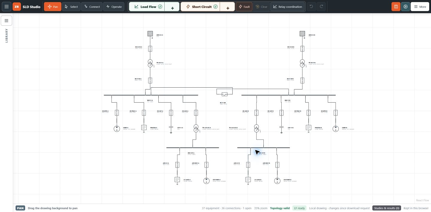
For an electrical engineer reviewing a plant extension, a maintenance team investigating repeated trips, or a student learning network studies, three questions belong together. How is the network operating? What happens during a fault? Which protection device should clear it?
Online short circuit analysis, load flow and relay coordination address different parts of that review. ZeroRiskk SLD Studio brings single-line diagrams, equipment inputs and these study workflows into a browser-based workspace. Here is what to prepare, what to inspect, and how to turn calculated results into a useful engineering review.
Three studies. Three different engineering decisions.
| Study | Question it addresses | What to review |
|---|---|---|
| Load flow | How does the network operate in this case? | Bus voltages, branch currents, equipment loading, active and reactive power, and losses. |
| Short circuit | What current can flow for the selected fault? | Fault location, fault type, connected sources, branch contributions and equipment duty. |
| Relay coordination | How should protection respond? | Pickup settings, time-current characteristics, grading and the intended trip sequence. |
A satisfactory voltage profile does not establish that switchgear has adequate fault capability. Similarly, an acceptable fault-current calculation does not establish selective protection. Each study answers part of the problem; the assumptions and operating cases must connect them.
Online short circuit analysis: look beyond the headline kA
Short-circuit current depends on the network seen from the fault location. The supply, transformers, conductors and connected sources influence the calculation. A fault at the main board and a fault at the end of a long feeder need separate attention.
For equipment-duty review, inspect the applicable maximum fault condition. For protection sensitivity, also examine the relevant minimum fault condition. A lower current can be harder for protection to detect and clear within the required time. One maximum kA value cannot answer both questions.
Keep these items beside the result:
- The faulted bus or equipment location and selected fault type.
- The source arrangement and operating case.
- The calculation method and assumptions used.
- The reported current quantity and the equipment rating being checked.
- Missing inputs, assumed values and unresolved validation messages.
Compare like quantities. A breaker’s interrupting rating, making capability and short-time withstand describe different duties. RMS fault current and peak making current are different quantities; short-time withstand also has a stated duration. Review the applicable manufacturer data and project requirements before declaring equipment suitable.
Schneider Electric’s guide to minimum short-circuit current explains why interrupting capability and clearance of lower fault currents both matter. Its circuit-breaker characteristics guide explains relevant rating terminology.
Online load flow analysis: understand the operating case
A load flow study calculates a steady-state operating condition for the modeled network. It helps identify where voltage, current or loading deserves attention before equipment is added or an operating arrangement changes.
Start with the actual supply arrangement. Which transformers are in service? Is the bus coupler open? Which generators are connected? What load and power factor belong to this case? A well-drawn diagram with incorrect switching states can answer the wrong question convincingly.
Read results as a connected picture. A low bus voltage may sit alongside a heavily loaded transformer, a long feeder or substantial reactive-power demand. Investigate the model and compare operating cases before deciding on a remedy.
For a guided introduction with an editable practice network and equipment worksheet, follow the first load flow study in SLD Studio. Keep the original case before changing loads, generation or network connections.
Online relay coordination: connect fault current to the trip sequence
A coordination study examines whether protection can isolate the faulted section while preserving the intended upstream backup. Time-current curves make the relationship visible, but the curves need the correct current basis and actual device settings.
Check the CT ratio, relay pickup, curve family, time multiplier or time dial, instantaneous elements and breaker operating time. Distinguish primary amperes from relay secondary amperes. Record the devices and trip connections represented by each curve.
Review the relevant current range and operating arrangements. Two curves separated at one fault current may have an inadequate margin elsewhere. A change in source availability can also change the current seen by each relay.
Normal load, motor starting and transformer energisation introduce additional constraints. Selectivity must be balanced against sensitivity and equipment protection; simply increasing upstream delays is not a universal solution. The required margin depends on the devices, tolerances, clearing times and protection philosophy.
For the underlying principles, SEL’s distribution protective devices course covers coordination, overcurrent elements and time curves. Its technical paper on adaptive inverse-time elements discusses how operating arrangements can affect coordination.
Prepare these inputs before running a study
Useful results begin with traceable data. Mark an unavailable value as an assumption rather than silently treating a typical value as verified.
- Network: current SLD, voltage levels, normally open points and intended operating cases.
- Supply: utility fault-level information and relevant source or generator parameters.
- Transformers: rating, voltage ratio, impedance, vector group, tap position and earthing information.
- Cables and lines: length, conductor details, impedance and parallel arrangements.
- Loads: active and reactive demand, or the specified rating and power factor, with the demand basis stated.
- Protection: device model, CT data, existing settings, characteristic curves, breaker timing and trip connections.
The exact fields depend on the selected study and modeled equipment. Where ground faults are involved, review the earthing and zero-sequence data carefully.
A practical workflow: adding a motor feeder
Consider a plant planning an additional motor feeder from an existing distribution board. This is an illustrative review sequence, not a calculated ZeroRiskk result.
- Establish the base case. Reconcile the model with the current SLD, operating arrangement and available measured data.
- Review load flow. Compare the existing and proposed running conditions. Inspect bus voltage, feeder current and transformer loading. Assess motor starting separately where the scope requires it.
- Review fault conditions. Check the board and remote feeder location under relevant source arrangements. Compare the appropriate results with equipment duty and protection sensitivity.
- Review coordination. Examine the proposed feeder protection against upstream devices and the motor’s operating requirements.
- Document the decision. Retain inputs, assumptions, findings and outstanding actions with the case being reviewed.
This sequence makes a proposed change easier to explain: the operating effect, fault duty and protection response remain tied to the same network.
What makes a study result ready for review?
A useful report identifies the project, revision, operating case and calculation scope. It makes assumptions and unresolved findings visible, rather than presenting a clean result page that hides uncertain inputs.
Retain the model alongside the report. Record changes between cases and check that equipment identifiers match the site documentation. Software calculations support engineering decisions; they do not themselves authorise commissioning or changes to live relay settings. Project-specific review and the applicable testing and approval process still matter.
Questions before your first online study
Do I need to sign in to run studies?
Yes. Numerical study runs in SLD Studio require sign-in. Review the displayed study requirement in the workspace before running your case.
Can I start without a completed plant model?
Use the practice network and equipment worksheet to learn the workflow. Teaching inputs and example results are not an approved installation design.
Does load flow replace a short-circuit study?
No. Load flow examines an operating condition. Short-circuit analysis examines fault conditions, and coordination examines the protection response. Choose the studies needed for your engineering question.
Can I apply relay settings directly from a study report?
A report is an input to the project review. Confirm the actual devices, CT circuits, settings, trip connections and required tests through the site’s approval process before implementation.